1
Circuit & PCB
Selected components under budget/size/power constraints. Designed circuit schematics, took the boards from pcb layout to fabrication and assembly.
Orbit is a modular desk controller / productivity hub that explores physical controls, swappable input modules, and intuitive UI for tactile digital workflows.
01 / Overview
A modular productivity console designed to reduce distractions.
Because small distractions add up.
02 / My Contribution
Orbit was a senior design project (SDP) built by a team. My work spanned the electronics, system design, mechanics, and software — this is what I specifically owned.
Selected components under budget/size/power constraints. Designed circuit schematics, took the boards from pcb layout to fabrication and assembly.
Defined the I²C event architecture linking ESP32-S3 modules to the Raspberry Pi host, including hot-swap attach-detach behavior under test.
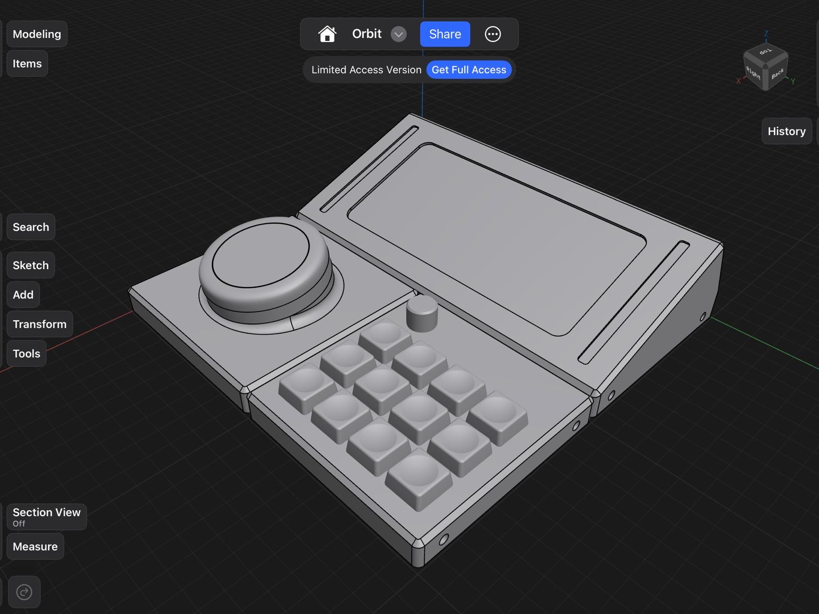
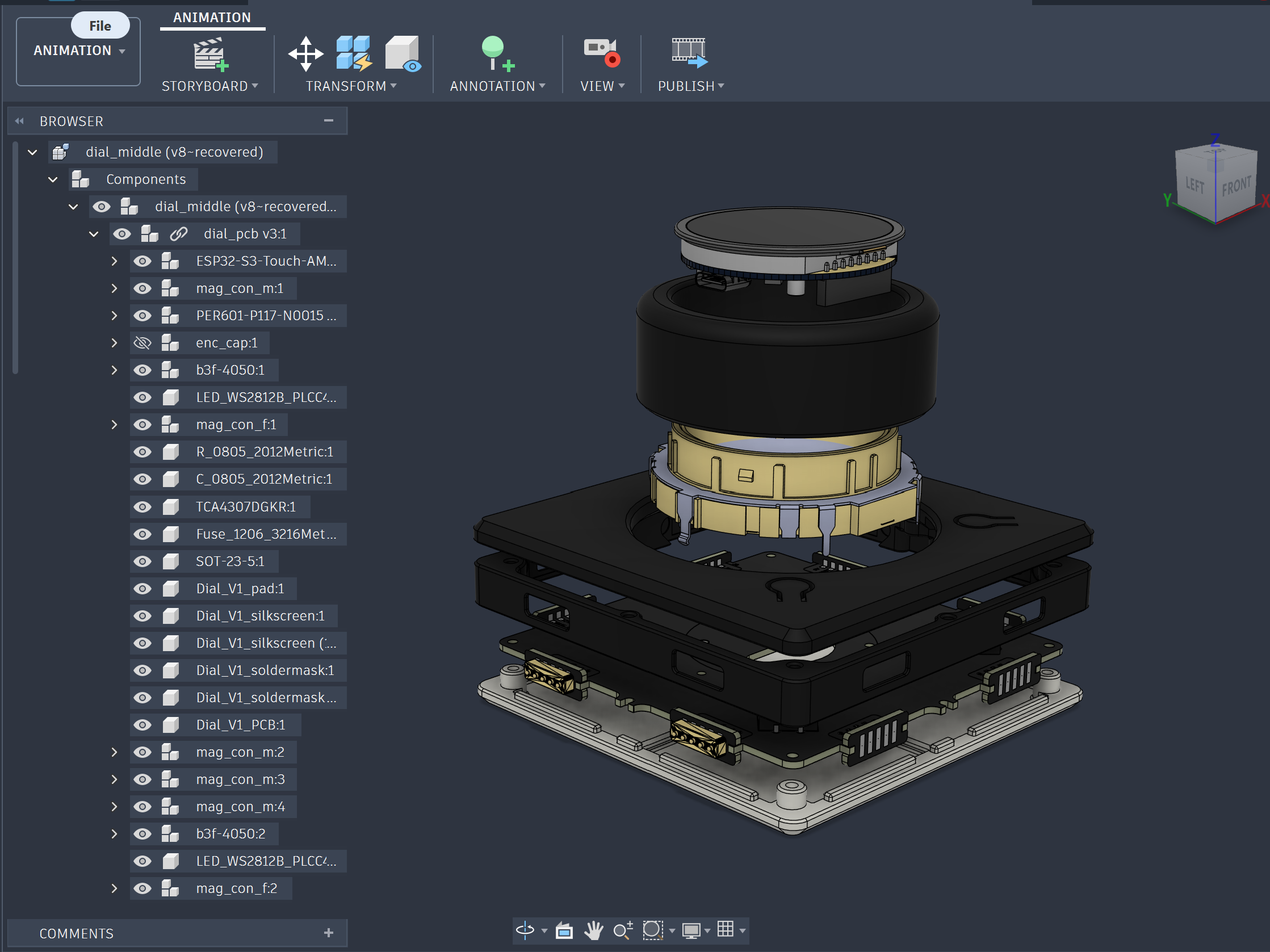
Designed enclosures in Fusion 360 from PCB STEP files, 3D-printed using various materials like PLA for cases, PC for translucent underglow base and SLA resin for the keycaps.
Wrote ESP32-S3 module firmware to collect various user inputs(switches and encoders) and host-side event routing for Macropad and Dial modules in C/C++.
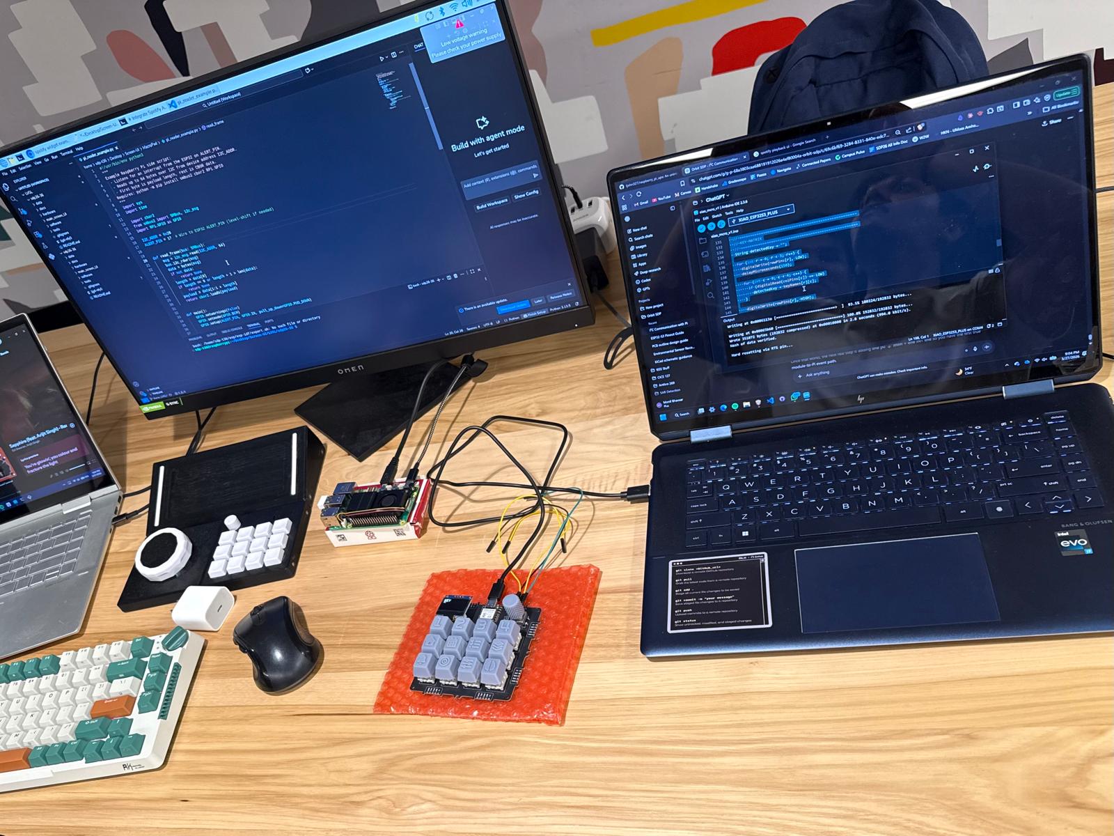
Assembled and bench-tested modules, debugging the I²C bus, pogo-pin communication with a logic analyzer and scope and measured power draw of modules.
Generated BOMs from PCB layouts, tracked budget against component choices, documented build decisions in the GitHub repository, recorded weekly meeting notes with faculty advisor.
03 / System Architecture
Modules read inputs and emit events over I²C; the host owns profiles, UI state, and output actions.
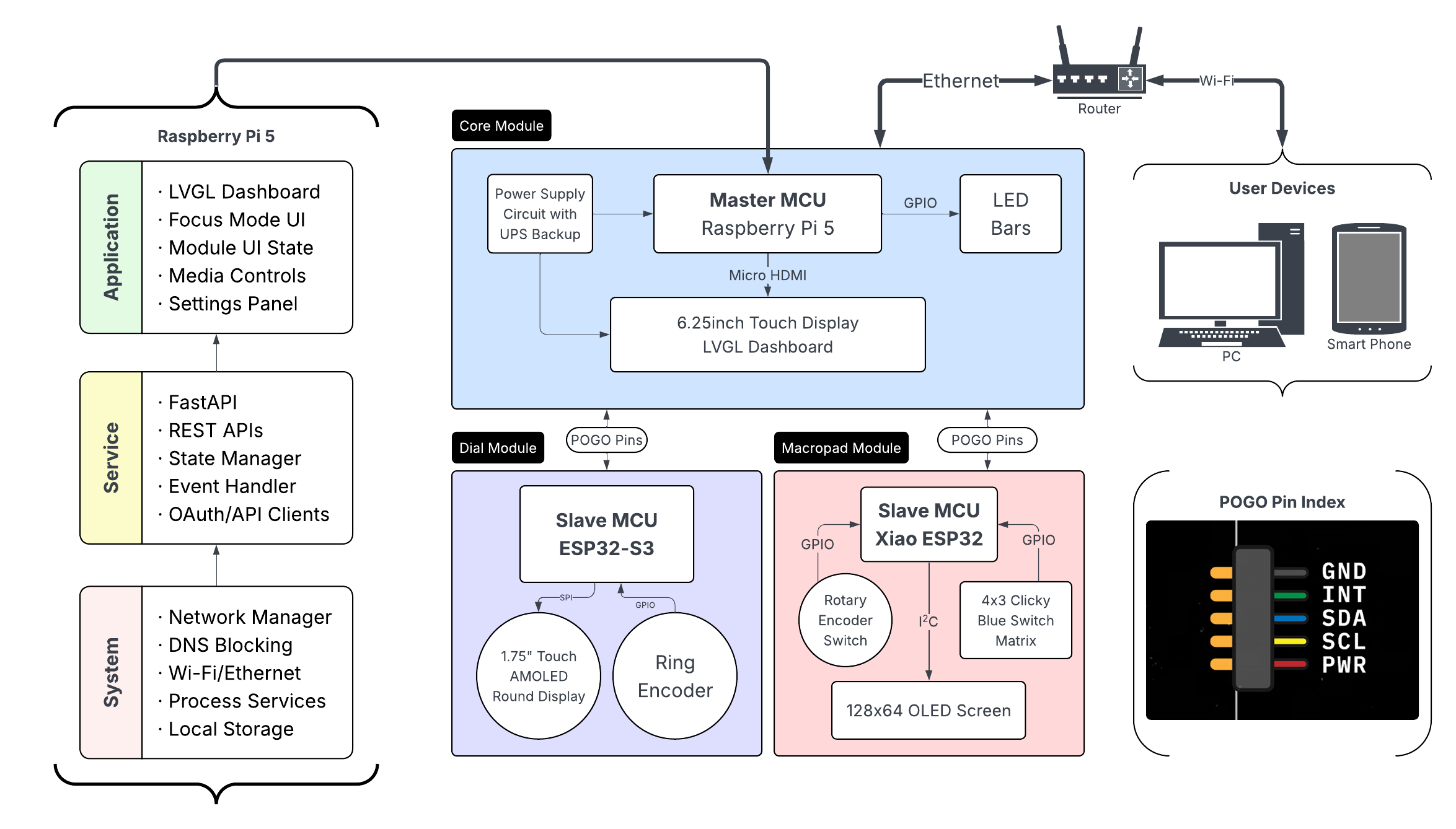
System architecture (Hardware Flowchart)
04 / Modules
Orbit separates processing from interaction: the core handles coordination and decision-making, while each module captures physical input and sends it back through a shared interface.
The brain of Orbit.
Runs the interface, manages connected modules, and keeps every interaction fast, synchronized, and context-aware.
Runs Orbit's UI, application logic, and profile management.
Detects connected modules and routes every input to the correct action.
Updates every module based on the active application and workflow.
Communicates with external services, devices, and FocusMode.
Keeps peripheral modules lightweight while allowing new modules to be added without redesigning the system.
Continuous control without hunting through menus.
Designed for adjustments that benefit from precision and muscle memory.
Scroll through long documents, timelines, and code naturally.
Control volume, brightness, zoom, brush size, and other continuous values.
Integrated display provides contextual information without switching windows.
The same dial performs different actions depending on the active application.
Frequently used controls stay within reach while your other hand remains on the keyboard or mouse.
Dedicated shortcuts for repetitive work.
Frequently used actions become physical buttons instead of keyboard shortcuts you have to remember.
Launch macros, shortcuts, and automations instantly.
Key mappings automatically change with the active application.
Display shows the current profile and available shortcut layer.
Reduce repetitive clicking and menu navigation during everyday work.
Create layouts optimized for productivity, creative software, development, or media control.
07 / Timeline
How I took Orbit from an early product idea to a working modular system — defining the experience, selecting the architecture, building the hardware, and learning through each prototype.
 1 / 3
1 / 3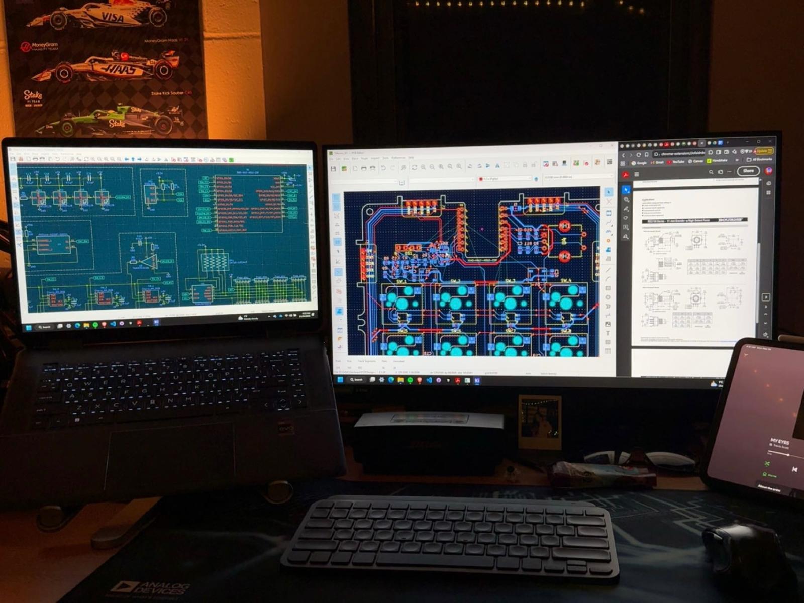
08 / Demo Day
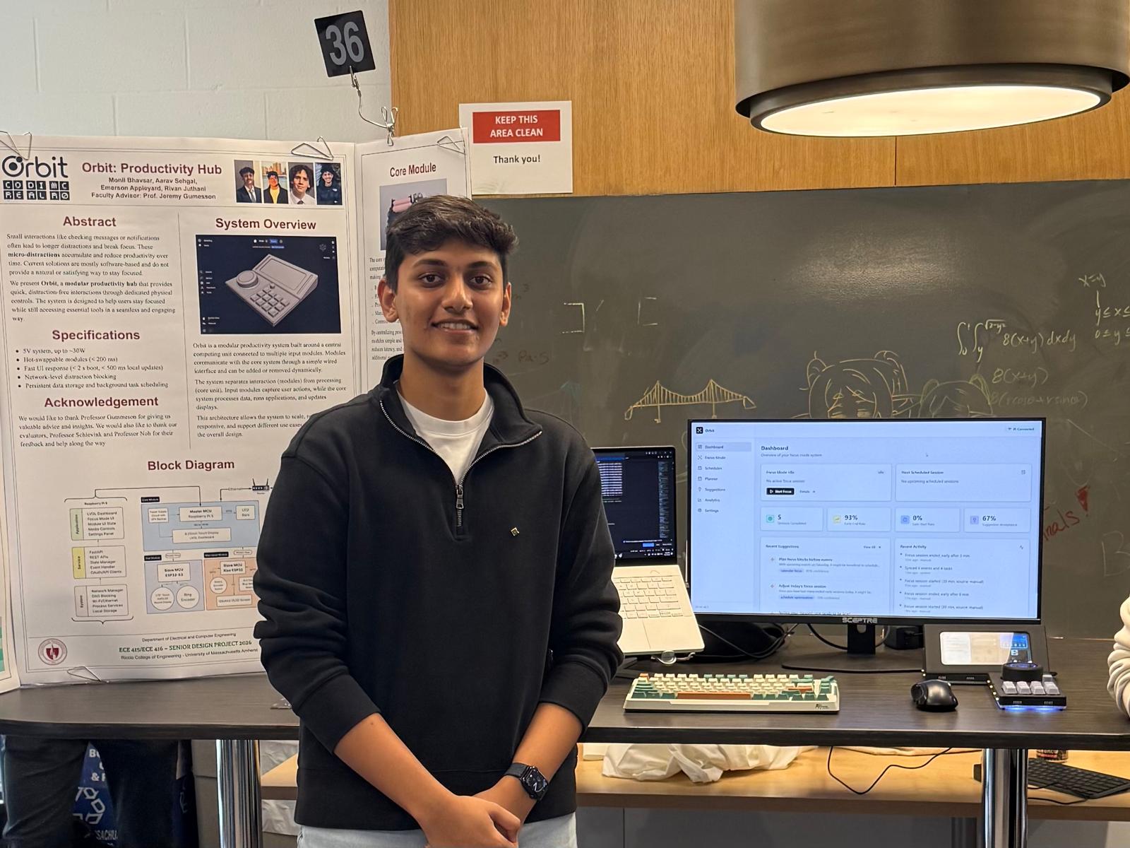
Orbit was shown at the senior design demo day to faculty, peers, and the community. Below is real audience feedback alongside the recognition it received.
I wish I had this on my desk. During meetings or deep work, I get distracting emails all the time, and it is hard to tell what actually needs my attention.
I would use this in my dorm all the time. One Instagram notification can turn into scrolling, so having a physical device that keeps me focused makes a lot of sense.
The design looks professionally manufactured. I honestly could not tell it was 3D printed because the finish and form factor felt so refined.
This fits the way I like to work. I like having quick controls and a dedicated setup for staying productive instead of digging through apps.
I would get this for my kid. It feels like it could help students stay organized and avoid getting pulled into social media while trying to work.
The tactile feel is what makes it interesting. Most productivity tools are just software, but this gives you a physical sense of control.
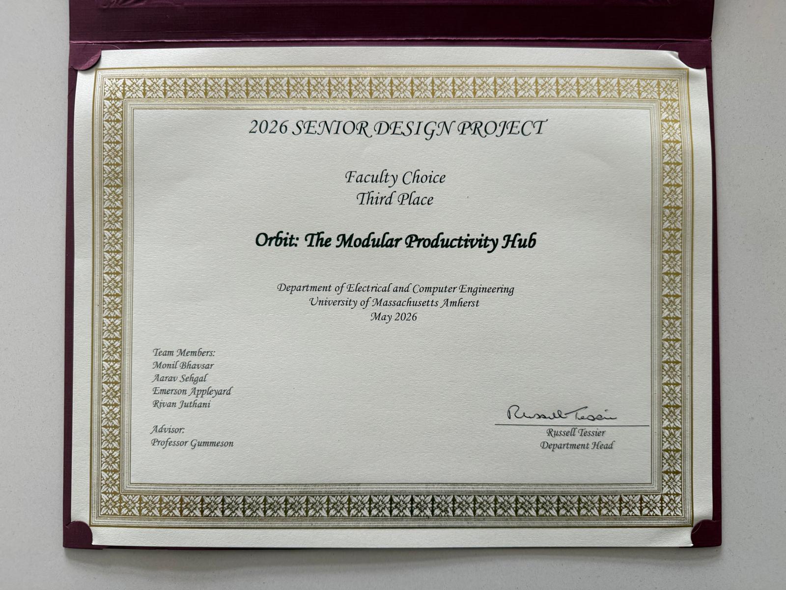
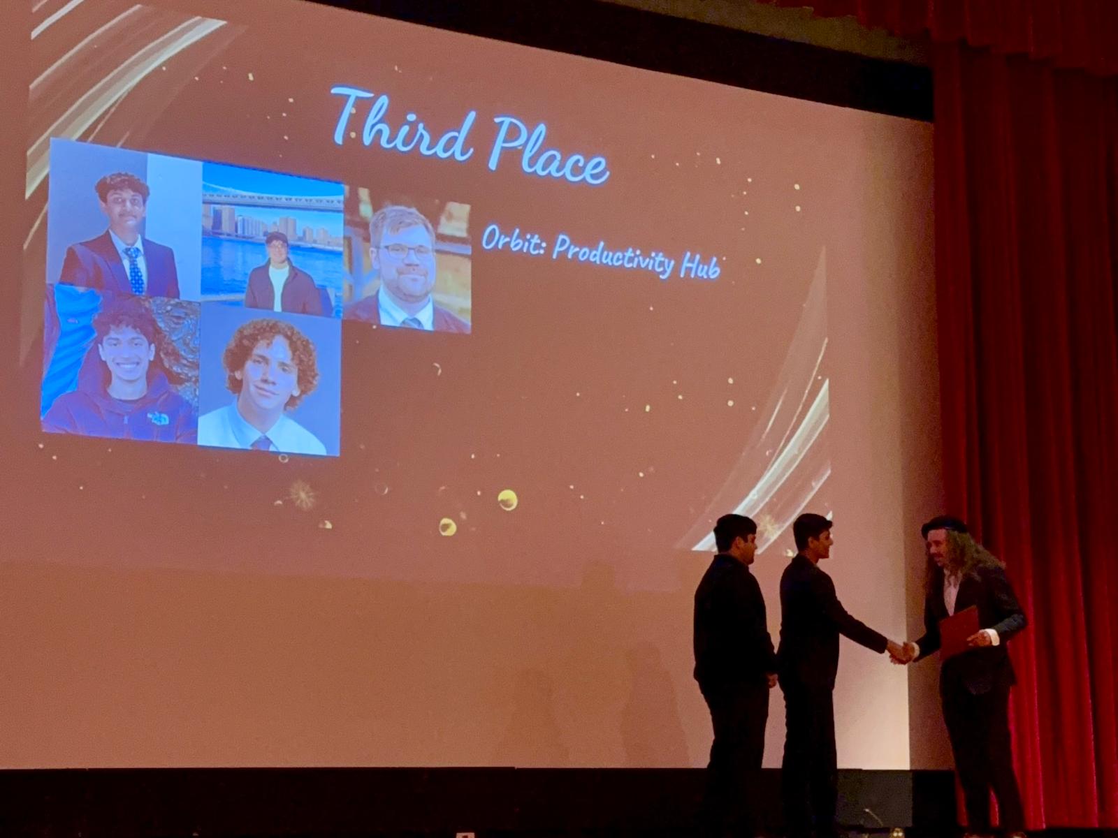
Faculty Choice — Third Place, UMass ECE Senior Design Project Demo Day.